Power Factor Meter Wiring Diagram

Honda Xr200 Wiring Diagram, Skygo150 Voltage Regulator for XR200/Actual Wiring/Honda XR200 Modified/Supermoto/DIY Garage PH, 10.03 MB, 07:18, 10,383, D I Y Garage PH, 2021-01-23T08:48:03.000000Z, 19, Iam looking for a 1982 honda xr200 wiring diagram, www.justanswer.com, 904 x 703, jpeg, wiring diagram 1982 honda xr200 xt200 yamaha manual iam motorcycle looking 1981 mechanic bikee wire, 20, honda-xr200-wiring-diagram, Anime Arts
Power factor meter wiring diagram. By | june 11, 2015. What is power factor meter definition types circuit globe dynamometric 1ph 3ph automatic electric ltd physical wiring diagram of electronic paper 47 ways to wire your wrong kele com electrical guide portable 2039 yokogawa test measurement corporation meters electrodynamometer. Meter form drawings, provided by durham company.
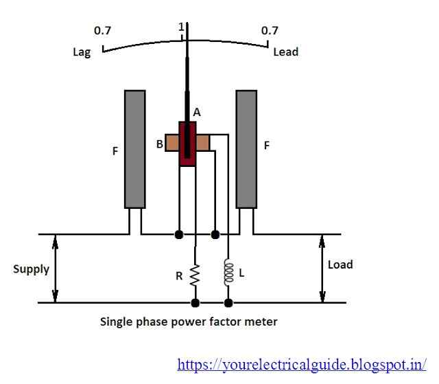
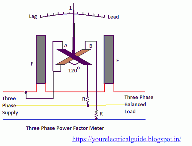
170 x 120 x 120: 220 x 120 x 120: 170 x 170 x 65: 245 x 170 x 65: 220 x 150 x 75: 260 x 150 x 75 Here in the construction of this power factor meter we divide the current coil into two equal parts since it is the current coil. The general circuit diagram of single phase electrodynamometer power factor meter is given below. I would like to adjust this circuit to measure the power factor and phase shift of a capacitive load using online simulator.
Power Factor Meter - your electrical guide

Digital power factor meter circuit diagram composed of ICL7107 under Repository-circuits -51069
Power Factor Meter - your electrical guide

Power Factor Meter - your electrical guide

Single phase power factor meter - YouTube

Power Factor Meters | Electrodynamometer Type Power Factor Meter | Electrical4U

Power Factor Meter Principle - Inst Tools

DELIXI Instruments & Meter Co.,Ltd
Power Factor Meter Schematic - CircuitLab
Electrodynamic Power Factor Meter - Single phase and Three Phase Power Factor Meter
