Vehicle Alternator Wiring Diagram
12 volt alternator wiring diagram. Click on each one to enlarge it use the relevant diagram along with the supplied written instructions to check your wiring and connections during and after installation and a wiring diagram is a simplified conventional pictorial representation.

16+ Mopar Alternator Wiring Diagram Alternator, Diagram, Car alternator
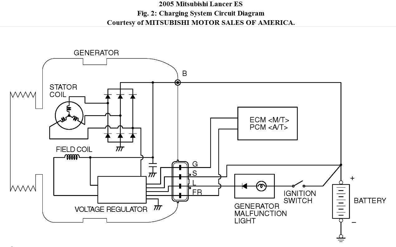
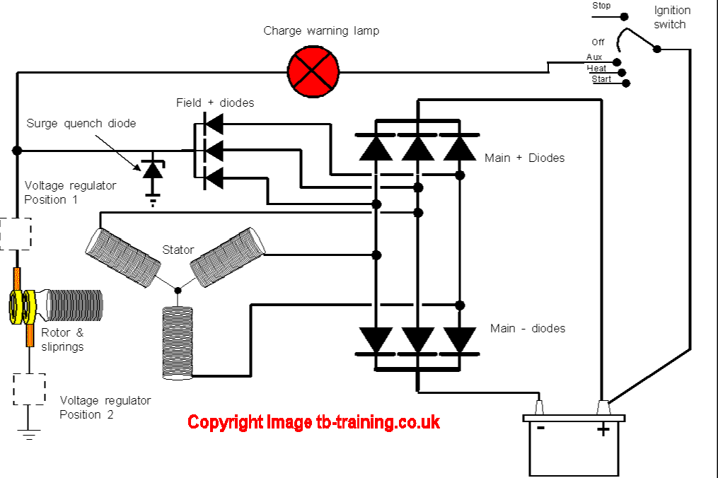
Here the basic internal circuit diagram of the car alternator and the wiring diagram of the alternator with battery is given below.
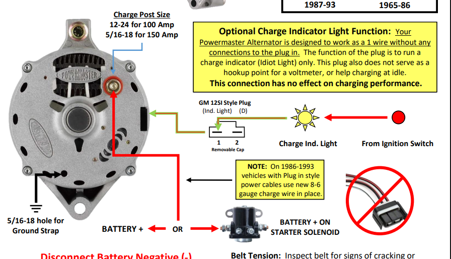
Vehicle alternator wiring diagram. Figure 1, below, is a block diagram, or a functional diagram, of an alternator, and its connections to the remainder of the automobile electrical system. Attach the regulator to the shock tower by connecting the black wiring without the loop to a mounting screw and then install the plug with pigtails for the regulator and make sure that there is good grounding. Alternator exciter wiring diagram loop the red wire off the plug to the post on the rear of the alternator.
It represents the physical parts of the electrical circuit as geometric forms, with the real power and connection connections in between them as thin sides. This is the same place the red wire from the da plug connects. Trace the wiring till you can see where a short may have taken place.
First, you can't run to the same side, since with the 12 volt conversion, we are going to use. And if there isn't one, i connect the exciter wire to the ignition circuit, thru. The points at which the two wires connect to the solenoid to alternator cable are about 23 1 8 apart.
4 pin alternator wiring diagram. When you make use of your finger or perhaps the actual circuit with your eyes, it is easy to mistrace the circuit. Highlight the individual circuit using a different color for positive and negative.
This diagram was designed for 12 volt systems, but can also be used for 6 volt systems. 4 wire alternator wiring diagram. Blow the horn and watch the needle jump.
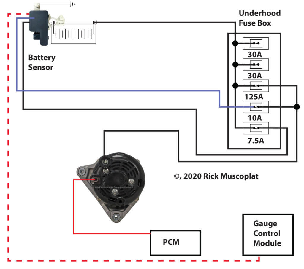
This rotor spins past wire coils causing a magnetic field. The circuit comprises three main wires: How to wire an external voltage regulator on a gm vehicle.
The alternator supplies power for the vehicle when the engine is running and engine speed is above idle. Take the other end of the long red wire and connect directly to one terminal of. It is really simple to draw a wiring diagram;
First , find the problem area on the wiring diagram. Most modules use an internal driver to turn the alternator’s field circuit on and off. The other terminal is the exciter.
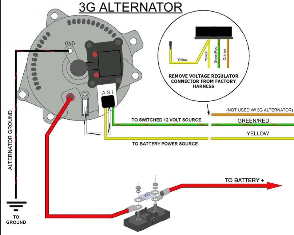
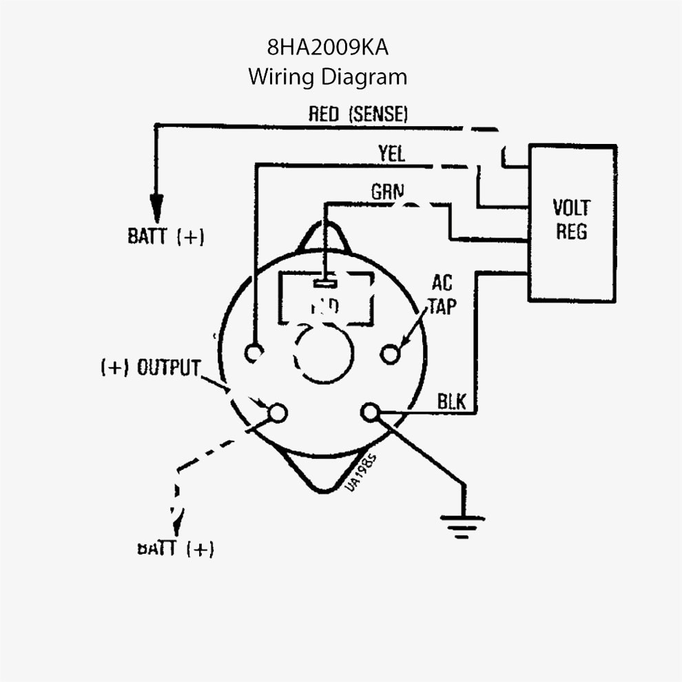
If you are able to look at a manufacturer's diagram of the alternator's connectors, the wire that slides over pin 1 of the alternator leads to the positive (+) connection on the vehicle's battery and senses voltage. • s is used by the regulator to monitor charging voltage at the battery. If used for 6 volt, make all the wires heavier by 2 gauges.
• b is the alternator output wire that supplies current to the battery. You simply require to have a great comprehension on. The yellow wire b coming from the charge side of the ammeter goes through the wiring harness and ties into the 10 awg cable which goes between.
Print the wiring diagram off plus use highlighters to trace the signal. Alternator wiring inspect wires and connections at the alternator. Understanding the alternator • four wires connect the alternator to the rest of the charging system.
Eliminate each portion of the diagram in sections until you find the short in the wiring. 4 pin alternator wiring diagram wiring diagram is a simplified adequate pictorial representation of an electrical circuit. Figure 1 below is a block diagram or a functional diagram of an alternator and its connections to the remainder of the automobile electrical system.
Battery positive cable, voltage sensing wire, and ignition wire. Step #7 (figure 1) take the long red 10 gauge wire and connect to the back of the alternator 10/32 stud. Chevy 4 wire alternator wiring diagram you will need an extensive expert and easy to comprehend wiring.
It looks like you are using the wiring diagram for a internal regulator alternator but using a. • ig is the ignition input that turns on the alternator/regulator assembly. The troubleshooting flow diagram on the next page lists the most common charging system problems, the possible cause, and.
It’s supposed to assist all the typical user in developing a suitable method. For example 14 gauge wire will become 12 gauge, 10 gauge will be 8 gauge, etc. Following the figure is a description of the various components that make up an alternator, and a description of how each operates to keep the battery charged in your car.
Here the basic internal circuit diagram of the car alternator and the wiring diagram of the alternator with battery is given below. White wire says to alternator regulator exciter. 1 trick that we 2 to printing a.
How to wire your hot rod. Step 4 connect the ammeter to the alternator. You can save this graphic file to your own device.
These guidelines will likely be easy to grasp and apply. Figure 1 below is a block diagram or a functional diagram of an alternator and its connections to the remainder of the automobile electrical system. This connector is manufactured so it may be inserted into the connector socket on the alternator one way only.
Wiring diagram arrives with several easy to stick to wiring diagram directions. The ignition input wire is attached to the engine. Gm alternator identification car alternator alternator automotive.
Mecc alte avr wiring diagram sr7 for alternator in generator parts. The alternator charge wire routes direct to the battery and not through any switch connection the alternator.

Simple alternator wiring diagram Alternator, Car alternator, Automotive repair

General Electric Voltage Regulator Wiring Diagram schematic and wiring diagram in 2020 Car

Automotive Alternator Wiring Diagram Boat electronics Pinterest Diagram, Cars and Car repair
1 wire alternator conversion Page 2 Ford Truck Enthusiasts Forums

Car Alternator Diagram Alternator wiring diagram, Car alternator, Alternator

Old Car Alternator Wiring Diagram Electrical Winding wiring Diagrams

Single Wire Alternator Wiring Diagram Alternator, Car mechanic, Automotive mechanic
Honda alternator and charging systems explained — Ricks Free Auto Repair Advice Ricks Free Auto
Alternator Wiring Hi, I Need Help in Determining What Is the Use
Alternator Circuit Wiring Diagram Database Wiring Diagram Sample
Chevy 4 Wire Alternator Wiring Diagram Wiring Diagram

1989 Chevy S10 Alternator Wiring Diagram Alternator, Electrical circuit diagram, Car alternator
1973 F250 OneWire Alternator Wiring Help Ford Truck Enthusiasts Forums

Denso Alternator Wiring Schematic Free Wiring Diagram

Delco Alternator Wiring Diagram Collection

12+ Car Alternator Voltage Regulator Wiring Diagram Car Diagram in 2020

240Z Alternator Upgrade WoodWorkerB
Technical Alternator install help/tips & suggestions/ The H.A.M.B.
Wiring Diagram Gm Alternator